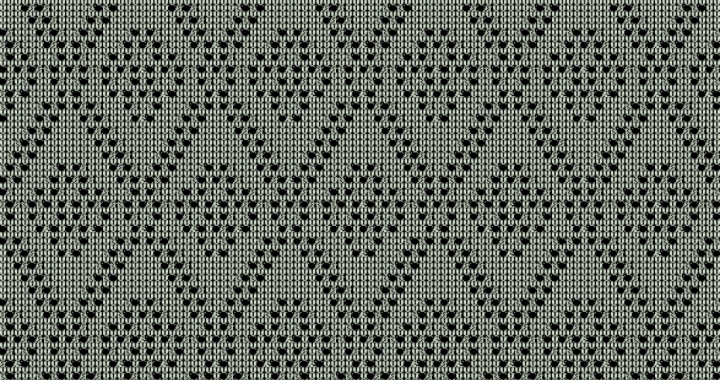
This is a 24-stitch version of the classic Rose Trellis stitch pattern suitable for punchcard knitting machines with transfer-only lace carriages (i.e., Brother).
Tag Archives: knitting
Rose Trellis Stitch Pattern From Brother Stitchworld Volumn III (pattern #155)
This is Brother’s version of the classic Rose Trellis stitch pattern. It’s not quite identical to the hand-knit original. The motif at the center of the X’s uses one-stitch transfers instead of multi-stitch transfers.Continue reading
Rose Trellis Stitch Pattern (Hand-Knit Version)
There’s an MKAL in progress on Ravelry where some of us are trying to knit the Ultra PimaRose Trellis Shawl Vest from Cascade Yarns.Continue reading
How Much Yarn Do I Need?
One of the questions that comes up a lot on Ravelry is “I have a cone of yarn that weighs this much… is it enough to make a sweater?”
The general rule of thumb is that a sweater takes about 1500 yards, but the fact of the matter is there’s no way to give any reasonable answer without having a lot more information. Not only does the yards per gram differs among fibers, the number of yards in a 1-pound cone depends on the size of the strand and in some cases, the spinning system used to manufacturer the yarn.
However, there is something you can do to get a pretty good estimate.
First, you must knit a swatch. That shouldn’t be a problem because you always knit a swatch anyway, right?
So knit a swatch thats big enough to get accurate measurements — about 80 stitches by 100 rows for finer yarns and 50 stitches by 60 rows for bulky yarns.
After washing and blocking the swatch the same way you’ll finish the completed garment, measure the length and width. You’ll also need to weigh the swatch to determine how much yarn it consumed.
Now you have all the information you need to determine the amount of fabric you can knit with the amount of yarn you have.
It’ll be easier to explain with an example, so grab your favorite calculator and follow along.
I have a cone of lovely but unidentified yarn that weights 600g. Most paper and plastic cones weight about 25 grams, so I really have about 575 grams of yarn.
My swatch is 8 inches wide, 4.5 inches long, and weighs 13g.
My sweater is roughly 38 inches around the body and 22 inches long. We don’t have to be exact here… rough measurements are ok. When in doubt, add an inch or so in both dimensions.
My sleeve is about 13 inches wide at the widest point and 23 inches long. Again, rough measurements are ok.
Let’s calculate the yardage for the body first. To make things easier, we’re going to work in one dimension at a time — first width, then length. I also want to err on the side of caution, so I’m going to round up to the nearest third or quarter (.25, .33, .50, .66, .75).
- The body is 4.75 times the width of my swatch (38 / 8 = 4.75), so a 38 x 4.5 rectangle needs 62g (4.75 x 13g).
- The body of my sweater is almost 5 times the length of my swatch (22 / 4.5 = 4.88), so a 38 x 22 rectangle needs 310g (5 x 62g).
Now let’s calculate the yardage for the sleeves using the same technique.
- The sleeve is about 1 2/3 times the width of my swatch (13 / 8 = 1.625), so a 13 x 4.5 rectangle needs 22g (1.66 x 13g).
- My sleeve is more than 5 times the length of my swatch (23 / 4.5 = 5.11), so a 13 x 23 rectangle needs 116g (5.25 * 22g).
- A sweater isn’t of much use with only one sleeve, so we need to double that to 232g (2 x 116g).
Now, we just add up the numbers to get the total yardage requirement: 310g + 232g = 542g.
Here’s a little cheat sheet you can print and keep with your yarn so you’ll have it handy the next time you need it:
Knitting Yardage Worksheet
| A = Swatch Width: | |
| B = Swatch Length: | |
| C = Swatch Weight: | |
| D = Desired Width: | |
| E = Desired Length: | |
| F = (D / A) * C: | |
| G = (E / B) * F = Total Yardage Required: |
Arduino Series: Working With An Optical Encoder
The Goal
I have an old White 1602 knitting machine that uses a light scanner to produce patterns in the knit fabric. The bed of the knitting machine syncs up with the controller via two obsolete rotary encoders and the stitch patterns are produced as a sequence of pulses causes specific needles to be selected.
The first problem is that the light scanner has a lot of mechanical parts that have deteriorated with age. Parts are no longer available.
The second problem is that the width of the pattern is constrained by the width of the mylar that feeds into the light scanner to product the pattern.
The third problem is that while the light scanner does its job well when it’s functioning, all of its capabilities could be performed more efficiently and accurately by a computer.
My goal is to completely replace the light scanner with newer technology. This post illustrates a prototype for how I might use an optical coder to track the position of the knitting carriage as well as when it changes direction.
Equipment
Arduino Mega 2560 R2
US Digital Optical Encoder S1-1250-I
4 male-to-female jumpers
Electrical tape
About The Encoder
While obsolete, the S1-1250-I encoder is a very capable piece of hardware, but much more expensive than what’s available on today’s market. I used it because I already had one, but the information presented in this post should work with any rotary quadrature encoder. I’ll most likely replace the US Digital with a SparkFun’s COM-11102 1024 P/R Quadrature Encoder I have on order.
About The Approach
There are basically two ways to interface with the encoder: polling and interrupts. A little project I’m playing with will require a considerable amount of accuracy, so I chose to use interrupts as polling might result in missed pulses.
Wiring
The encoder has 3 outputs: channel A, channel B and index. We’re not going to use index, so we need to make 4 connections — one for each of the two channels, one for power and one for ground. The encoder has raw wires so we need to add pins in order to attach it to the Arduino.
- Make sure the Arduino is powered off.
- Strip 1/4″ – 3/8″ of insulation from the encoder’s leads for power, ground, channel A and channel B.
- Insert the end of each wire into the female end of a jumper and secure with electrical tape.
- Connect the power lead to the 5V power pin.
- Connect the ground lead to one of the Arduino’s ground pins.
- Connect the channel A lead to digital pin 20. This pin is one of the 6 Arduino pins that support interrupts. The other pins with interrupts are 2, 3, 18, 19 and 21.
- Connect the channel B lead to digital pin 17.
The Code
/****************************************************************************************

Author:    Brenda A Bell
Permalink: https://www.brendaabell.com/2014/02/arduino-series-working-with-an-optical-encoder/

****************************************************************************************/

#define ENCODER0PINA         20      // this pin needs to support interrupts
#define ENCODER0PINB         17      // no interrupt required
#define CPR                  1250    // encoder cycles per revolution
#define CLOCKWISE            1       // direction constant
#define COUNTER_CLOCKWISE    2       // direction constant

// variables modified by interrupt handler must be declared as volatile
volatile long encoder0Position = 0;
volatile long interruptsReceived = 0;

// track direction: 0 = counter-clockwise; 1 = clockwise
short currentDirection = CLOCKWISE;

// track last position so we know whether it's worth printing new output
long previousPosition = 0;

void setup()
{

  // inputs
  pinMode(ENCODER0PINA, INPUT);
  pinMode(ENCODER0PINB, INPUT);

  // interrupts
  attachInterrupt(3, onInterrupt, RISING);

  // enable diagnostic output
  Serial.begin (9600);
  Serial.println("\n\n\n");
  Serial.println("Ready.");
}

void loop()
{
  // only display position info if has changed
  if (encoder0Position != previousPosition )
  {
    Serial.print(encoder0Position, DEC);
    Serial.print("\t");
    Serial.print(currentDirection == CLOCKWISE ? "clockwise" : "counter-clockwise");
    Serial.print("\t");
    Serial.println(interruptsReceived, DEC);
    previousPosition = encoder0Position;
  }
}

// interrupt function needs to do as little as possible
void onInterrupt()
{
  // read both inputs
  int a = digitalRead(ENCODER0PINA);
  int b = digitalRead(ENCODER0PINB);

  if (a == b )
  {
    // b is leading a (counter-clockwise)
    encoder0Position--;
    currentDirection = COUNTER_CLOCKWISE;
  }
  else
  {
    // a is leading b (clockwise)
    encoder0Position++;
    currentDirection = CLOCKWISE;
  }

  // track 0 to 1249
  encoder0Position = encoder0Position % CPR;

  // track the number of interrupts
  interruptsReceived++;
}
How It Works
Lines 8 – 12 define a few useful constants to make the code more readable. What they do should be obvious from the comments.
Lines 15 – 16 define global variables that will be modified by the interrupt handler.
Line 19 & 22 define other global variables we’ll use inside the Arduino loop.
The setup() function on line 24 configures our channel A and channel B pins for input, attaches an interrupt handler to channel A’s pin and configures the serial port so we can see some diagnostic output. Note that we’re going to interrupt on a rising state change so we know that the state of channel A will always be high when our interrupt is triggered. Using a rising or falling interrupt means:
- We always know the state of A without having to perform a read: A is always high in a rising interrupt and always low in a falling interrupt.
- Since we always know the starting state of A, we only have to test the state of B to determine direction and track the current position.
The Arduino loop() function on line 40 does nothing more than print some diagnostic information about what we’re reading from the encoder. To avoid chatter, the loop is tracking current values against previous values to we don’t print information we’ve already seen.
The interrupt handler on line 55 does all the heavy lifting:
- When the encoder is moving in one direction, the pulse from channel A is leading the pulse from channel B. When the encoder is moving in the other direction, the pulses are reversed.
- When the state of A and B are equal, B must be leading A, so the encoder is turning counter-clockwise. Otherwise, A is leading B, so the encoder is turning clockwise. Remember when we configured our interrupt to fire on rising? The state of channel A will always be high, so we only need to check the state of channel B to determine direction.
- By comparing A to B instead of hard-coded constants, we can change the interrupt between rising and falling without breaking the interrupt handler.
The code on line 75 keeps the counter within the range 0 to 1249. This would allow us to compute angle or synchronize the position of the encoder to some other device.
The code on line 78 is an extra bit of diagnostic info we can use to track how many times our interrupt has fired.
Further Discussion
It’s much easier to understand how the interrupt handler works if you understand what’s happening when you turn the encoder shaft and reverse direction.
When you turn the encoder’s shaft clockwise, A is leading B. This results in 4 distinct transitions that are repeated over and over as long as the shaft continues rotating in the same direction.
| A | B |
|---|---|
| HIGH | LOW |
| HIGH | HIGH |
| LOW | HIGH |
| LOW | LOW |
What’s important is this:
- The inputs are latched, meaning that when we read B’s value from A’s interrupt handler the value we get is B’s state as it existed at the time the interrupt handler was fired.
- The handler is fired when A goes high.
- When the shaft is turning clockwise, the handler is fired between the first two transitions —before B goes high — so we know the shaft is rotating clockwise when A is high and B is low.
If the shaft is turning clockwise and you stop turning, A remains high and B remains low.
If the shaft then starts turning counter-clockwise, B is leading A. This means that B has to go high before A’s interrupt fires again. Therefore, when both A and B are high, the shaft must be turning counter-clockwise.
Some makers may be inclined to use interrupts on both A and B. Unless you have an application where you absolutely must perform some action between A and B going high in both directions, the second interrupt is completely unnecessary. Interrupts are an expensive, limited resource so it’s wise to only use them when you need them.
References
http://playground.arduino.cc/Main/RotaryEncoders#Example1
Machine Knitting: Increasing Evenly Across the Row
First, you need to figure out where the increases go. Suppose you have 98 needles in work and the pattern says increase 13 stitches evenly across the row.
Compute the approximate placement of the decreases using the following formula:
(current # stitches - # to increase) / # to increase

(98 - 13) / 13

85 / 13

6.53 rounded down = 6
This tells us we need to space our increases approximately 6 stitches apart.
Determine where to start based on whether you’re increasing by an even or odd number of stitches. If the number of increases is even, position the two center-most increases on either side of center. E.g., if the distance between increases is 6 stitches, the two center-most increases would be on needles 4L and 4R, leaving 6 stitches (3L to 3R) in between.
If the number of increases is odd, position the center increase on either side of center (1L or 1R).
Determine the placement of the other increases by counting off needles working from the center towards the edges. For this example, you would leave 6 stitches between each increase. Temporarily mark the location of each increases by pulling those needles to hold.
Use a garter bar or decker comb to move stitches right or left starting at the edge. You may have to make several passes if your decker comb is not wide enough to transfer all of the stitches at once.


